Reports of Investigations
-
Books & Reports
- Reports of Investigations
- Guidebooks
- Udden Series
- Geological Circulars
- Down To Earth
- Atlases of Major Oil and Gas Reservoirs
- Texas Memorial Museum Publications
- Environmental Geologic Atlas of the Texas Coastal Zone
- Mineral Resource Circulars
- Other Reports
- Seminars and Workshops
- Handbooks
- Submerged Lands of Texas
- Symposia
- Annual Reports
- Open File Reports
-
Maps & Cross Sections
- Thematic Maps
- Miscellaneous Maps, Charts & Sections
- Geologic Atlas of Texas
- STATEMAP Project Maps
- Geologic Quadrangle Maps
- Cross Sections
- Highway Geology Map
- Energy and Mineral Resource Maps
- Shoreline Change and Other Posters
- Wilcox Group, East Texas, Geological / Hydrological Folios
- Bouguer Gravity Atlas of Texas
- River Basin Regional Studies
- Featured Maps
- Posters
- Teachers & the Public
-
Geological Society Publications
- Gulf Coast Association of Geological Societies
- Alabama Geological Society
- Austin Geological Society
- Corpus Christi Geological Society
- Houston Geological Society
- Lafayette Geological Society
- Mississippi Geological Society
- New Orleans Geological Society
- South Texas Geological Society
- GCS SEPM Publications
- Historic BEG & UT Series
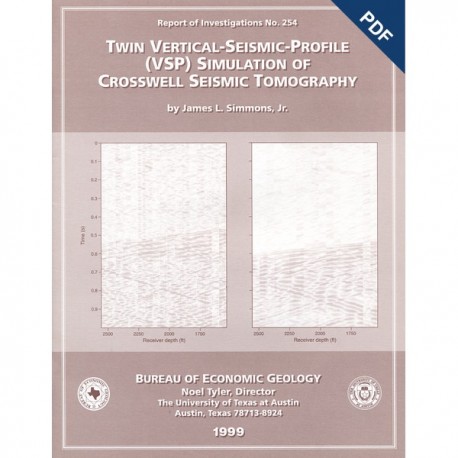
Twin Vertical-Seismic-Profile (VSP) Simulation of Crosswell Seismic Tomography. Digital Download
RI0254D
For a print version: RI0254.
RI0254D. Twin Vertical-Seismic-Profile (VSP) Simulation of Crosswell Seismic Tomography, by J. L. Simmons, Jr. 35 p., 19 figs., 1999. doi.org/10.23867/RI0254D. Downloadable PDF.
To purchase this publication in book format, please order RI0254.
ABSTRACT
Researchers in crosswell seismic tomography attempt to image interwell velocity fields by using traveltimes of transmitted waves generated by a downhole source and recorded by downhole receivers. These traveltimes are governed by subsurface velocities along their travel paths, which in turn provide the basis for adjusting an initial-velocity model such that the traveltimes predicted by ray tracing best-match observed traveltimes.
Twin-vertical-seismic-profile simulation of crosswell (TVSC) tomography uses the first-arrival timesfrom wavefields generated by a number of surface sources positioned inline with two receiver wells. The differential traveltimes between receiver wells are used to estimate interwell velocities. As a result, TVSC tomography is theoretically independent of subsurface velocities outside the interwell space, although the vertical seismic profile (VSP) wavefields traveled through these parts of the subsurface.
TVSC tomography is evaluated on synthetic and real data. The velocity model is parameterized by cubic B-splines, and adjustments to the initial-velocity model are obtained by means of a least-squares solution. A model covariance matrix designed to minimize variations in spatial derivatives of the velocity updates is incorporated into the inverse problem.
The synthetic examples have differential traveltimes between receiver wells on the order of 70 to 80 ms. Velocities can be recovered from noise-free data having local errors as large as 2 percent and an associated data misfit of [plus or minus] 1 ms. Use of the model covariance matrix illustrates the trade-off between data fit and model reasonableness. Examples having Gaussian random noise as large as plus or minus 6 ms added to the differential traveltimes show local velocity errors as large as 5 percent, 95 percent of the data being predicted to within plus or minus 5 ms.
Field data were acquired at Texaco's Borehole Test Site located near Humble, Texas. Wavefields from four offset surface-source locations were recorded by six-element hydrophone arrays (10-ft receiver spacing, 50-ft maximum recording aperture) in two receiver wells over a depth interval of 2,550 to 1,540 ft. Three-component geophone data recorded in a third well over a depth interval of 1,500 to 50 ft provide information on the common shot statics (plus or minus 3 ms) and overall shot reproducibility.
VSP data quality is quite variable. Overall signal-to-noise ratio ranges from 15.5 to 4.8 decibels (root-mean-square amplitude). The differential traveltimes (between receiver wells) are roughly 50 to 60 ms. Noise in the first-arrival times produced by tube waves and timing inconsistencies that occurred during data acquisition is on the order of plus or minus 5 ms.
TVSC tomography predicts the measured first arrival times to within plus or minus 5 ms. Inversion results obtained assuming low and high noise levels in the data illustrate the trade-off between data fit and model reasonableness. The resulting velocity estimate indicates an overall increase in velocity from 6,800 ft/s at 1,540-ft depth to 7,600 ft/s at 2,550-ft depth, with a sharp increase at 2,100 ft.
Surface-source to downhole-receiver traveltime inversion reproduces data to within plus or minus 3 ms, and it is less sensitive to noise than is the TVSC inversion. Velocity models estimated by TVSC and surface tomography inversions are similar.
Keywords: inversion, tomography, VSP
CONTENTS
Abstract
Introduction
TVSC Approach
General Inverse Problem: Maximum-Likelihood Approach
Model Parameterization
Forward Modeling: Ray Tracing
Frechet Derivatives
Model Covariance
Data Covariance
Synthetic Examples: Noise-Free Data
Effect of Noise
Application of TVSC Approach To Real Data
Field Test Site, Field Geometry, and Data Acquisition
Seismic Data
Initial-Velocity Model
TVSC Inversion Results
VSP Traveltime Inversion
Discussion
Conclusions
Acknowledgments
References
Figures
1. Cross section of an Earth model showing traveltime grid. expanded view of interwell region, reference times, and interwell traveltimes
2. Two-dimensional B-spline basis function and one-dimensional profile V(z) at fixed x showing overlap of the basis functions that superpose to produce a smooth V(z)
3. True slowness (velocity) model used in synthetic examples, closeup of true and initial slowness(velocity) models, and first-arrival times from source locations to wells 1 and 2
4. Slowness (velocity) estimates for synthetic examples
5. Slowness (velocity) error relative to the true velocity model
6. Initial and final data misfit for noise-free examples in figures 4 and 5 and histogram of Gaussian random noise, initial misfit, and final misfit for examples d and e in figures 4 and 5
7. Aerial photograph of Texaco Borehole Geophysics Test Site in Humble, Texas
8. Common shot gathers and common depth gathers, source location A to well 2
9. VSP's, source locations A, B, C, and D to wells 1 and 2
10. Data from geophones in cemented receiver well at selected depths
11. Traveltime deviations relative to respective average first-arrival times for sources B and C
12. Diagrammatic cross section of real data-acquisition geometry and first-arrival times for indicated source-receiver well combinations
13. Initial-velocity model and initial data misfit for surface-source receiver well tomography
14. Raypath coverage from source location to far receiver well
15. Estimated velocity models for interwell inversion
16. Data misfit for interwell inversion
17. Final-velocity model and data misfit for surface-source tomography
18. Velocity-model comparison
19. Initial data misfit compared with final data misfit after interwell and surface-source inversions
Citation
Simmons, J. L., Jr., 1999, Twin Vertical-Seismic-Profile (VSP) Simulation of Crosswell Seismic Tomography: The University of Texas at Austin, Bureau of Economic Geology, Report of Investigations No. 254, 35 p. doi.org/10.23867/RI0254D.
