Reports of Investigations
-
Books & Reports
- Reports of Investigations
- Guidebooks
- Udden Series
- Geological Circulars
- Down To Earth
- Atlases of Major Oil and Gas Reservoirs
- Texas Memorial Museum Publications
- Environmental Geologic Atlas of the Texas Coastal Zone
- Mineral Resource Circulars
- Other Reports
- Seminars and Workshops
- Handbooks
- Submerged Lands of Texas
- Symposia
- Annual Reports
- Open File Reports
-
Maps & Cross Sections
- Thematic Maps
- Miscellaneous Maps, Charts & Sections
- Geologic Atlas of Texas
- STATEMAP Project Maps
- Geologic Quadrangle Maps
- Cross Sections
- Highway Geology Map
- Energy and Mineral Resource Maps
- Shoreline Change and Other Posters
- Wilcox Group, East Texas, Geological / Hydrological Folios
- Bouguer Gravity Atlas of Texas
- River Basin Regional Studies
- Featured Maps
- Posters
- Teachers & the Public
-
Geological Society Publications
- Gulf Coast Association of Geological Societies
- Alabama Geological Society
- Austin Geological Society
- Corpus Christi Geological Society
- Houston Geological Society
- Lafayette Geological Society
- Mississippi Geological Society
- New Orleans Geological Society
- South Texas Geological Society
- GCS SEPM Publications
- Historic BEG & UT Series
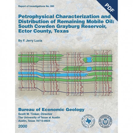
Petrophysical Characterization and Distribution of Remaining Mobile Oil... Digital Download
RI0260D
For a print version: RI0260.
RI0260D. Petrophysical Characterization and Distribution of Remaining Mobile Oil: South Cowden Grayburg Reservoir, Ector County, Texas, by F. J. Lucia. 54 p., 53 figs., 6 tables, 2000. doi.org/10.23867/RI0260D. Downloadable PDF.
To purchase this publication in book format, please order RI0260.
About This Publication
This report uses the rock fabric method to construct a reservoir model of a Permian Basin Grayburg dolomite reservoir. Rock fabrics are related to porosity, permeability, and capillary pressure and are distributed within a sequence stratigraphic framework. Key findings are that 1) remaining oil saturation is found in intervals with between 0.1 and 1 md, below perforated intervals, and between injection wells when no producer is present; 2) the best production comes from areas where anhydrite has been dissolved, creating a touching-vug reservoir; and 3) the presence of a 100-ft ROZ indicates that this reservoir is in imbibition mode, not drainage.
ABSTRACT
The South Cowden reservoir, a large Permian Basin oil field in Ector County, West Texas, produces from a dolomitized carbonate-ramp succession in the Grayburg (Permian) Formation. The field can be divided into a western area, characterized by interparticle porosity and by diagenetic products that conform moderately well to depositional textures, and an eastern area, characterized by interparticle and touching vug porosity and by poor conformance of diagenetic products to depositional textures.
Thin-section analysis demonstrates that the reservoir interval can be characterized by grain-dominated dolopackstones, medium crystalline mud-dominated dolostones, and a touching-vug pore system composed of dissolved-anhydrite nodules, fusumolds, and microfractures. Two rock-fabric-specific porosity-permeability transforms are defined, one for the grain-dominated and medium crystalline, mud-dominated dolostones and one for the touching-vug pore system.
In the western area the porous and permeable intervals conform to high-frequency cycles (HFC), and flow barriers occur at some cycle boundaries. In the eastern area, late dissolution of anhydrite has occurred, and no evidence has been found to relate the removal of anhydrite to HFC's. As a result, there is little conformance of petrophysical properties to HFC's, horizontal flow barriers are few, and pillars of impermeable anhydritic dolomite are scattered throughout the area.
The presence of a 100-ft residual-oil zone (ROZ) at the base of the reservoir downdip indicates that the downdip part of the reservoir is in imbibition rather than drainage capillary-pressure mode. Imbibition curves have lower water saturations in the productive interval and significantly smaller transition zones than predicted by drainage curves.
The initial water-saturation profile can be approximated by assuming that the base of the ROZ is the zero capillary-pressure level (zcpl). However, making this assumption will overestimate the volume of oil in the ROZ and transition zone. If the zcpl is placed above the base of the ROZ, the original oil in place will be understated. The ROZ is thought to have formed by remigration of oil as a result of eastward tilting during the Tertiary because a ROZ does not appear to be in the updip part of the field.
The three-dimensional distribution of remaining oil can be described by integrating permeability maps, vertical conformance of waterflooding from log analysis, and operational history. Intervals that have been invaded by floodwater are identified by comparing original-water-saturation estimates from capillary-pressure models with water saturation calculated from resistivity logs according to the Archie equation. Flooded intervals have more than 1 md permeability, and considerable volumes of movable hydrocarbons are located in zones having 1 to 0.1 md permeability. Not all of the greater-than-1-md rock is flooded, however. Unflooded high permeability is found (1) below perforated intervals, (2) between injection wells when injection and producing wells are located within a large area of high permeability, and (3) between producing wells and low-kh areas, even if an injector is in the low-kh area.
Keywords: capillary pressure, cyclicity, Ector County, Grayburg, imbibition, permeability, petrophysics, remaining oil, reservoir modeling, rock fabrics, South Cowden, Texas, water-saturation models
CONTENTS
ABSTRACT
INTRODUCTION
FIELD LOCATION AND HISTORY
GEOLOGICAL FRAMEWORK AND CYCLE CORRELATION
ROCK FABRICS
Description
Origin of Rock Fabrics
POROSITY CALCULATIONS
Neutron Logs
Acoustic Logs
WATER-SATURATION EST1MATIONS
Original Water Saturation from Capillary-Pressure Curves
Current Water Saturation from Archie Equation
TRANSITION-ZONE CONSIDERATIONS-THE IMBIBITION RESERVOIR
PERMEABILITY ESTIMATIONS
ROCK-FABRIC AND PERMEABILITY DISTRIBUTION
Small-Scale Variability
Variability at the High-Frequency-Cycle Scale
Areas 1 and 2
Area 3
Variability at the Reservoir Scale
LOCATION OF REMAINING-MOBILE-OIL SATURATION
Simulation Results
Kh maps compared with Production Maps
LOCATING UNTAPPED MOBILE OIL IN INFILL WELLS
3-D Distribution of Remaining Oil
Later lnfill Wells
CONCLUSIONS
ACKNOWLEDGMENTS
REFERENCES
Figures
1. Structure map on top of Grayburg. South Cowden field, showing production units and study area
2. lsopach map of cumulative production from original development wells in study area
3. West-east structural cross section A-A' of South Cowden reservoir, showing distribution of permeability and anhydrite alteration types
4. West-east stratigraphic cross section of South Cowden field, showing high-frequency sequences and cycles
5. Core descriptions from wells Moss Unit No. 16-14 and Emmons Unit No. 143, showing sequences and high-frequency cycles
6. Northwest-southeast cross section EB', showing examples of cycle correlations made by using gamma-ray logs that show good upward-shallowing cycles in cycles F1-F2 through F-Fx
7. Diagram illustrating South Cowden rock-fabric petrophysical classes
8. Photomicrographs of petrophysical rock fabrics
9. Photomicrographs of petrophysical rock fabrics
10. Photos of petrophysical rock fabrics
11. Comparison of average kh values obtained from cased-hole porosity logs run in several wells by five cased-hole logging companies
12. Cross plot of core porosity and open-hole neutron-log porosity values for seven wells
13. Cross plot of core porosity and cased-hole neutron porosity values for three wells
14. Cross plot of neutron-density porosity and transit time from acoustic logs, showing three groups of data related to pore type, anhydrite alteration, and porosity transform
15. Map showing distribution of interparticle, separate-vug, and touching-vug pore types on the basis of acoustic-porosity cross plots
16. Map of the distribution of altered sulfate and intervals of complete sulfate removal on the basis of core data from South Cowden field
17. Capillary-pressure graphs of three dolograinstones of varying porosity from the Moss Unit, compared with the generic class-1 capillary-pressure model
18. Petrophysical class-2 averaged capillary-pressure curves compared with curves calculated from the class-2 saturation model using identical porosity values
19. Comparison of class-3 averaged capillary-pressure curves with curves calculated from the class-3 saturation model
20. Comparison of capillary properties from the three petrophysical classes at similar porosity values
21. Comparison of model class9 capillary-pressure curve with two curves from class-2, touching-vug fabric, Emmons Unit No. 142
22. Cross plot of porosity- and log-calculated water saturation from Moss Unit No. 8-12, showing water-saturation-porosity transform used to calculate original water saturation above the transition zone
23. Comparison of capillary-pressure saturation model using a reservoir height of 350 ft with the saturation transform from Moss Unit No. 8-12
24. Calculated logs from MU 201 1, illustrating close agreement between class-2-model and Archie water saturation, where porosity is greater than 6 percent
25. Cross plots of porosity, water saturation, and rock fabric for the G interval
26. Part of Moss Unit No. 1722 well, illustrating method for estimating rock fabric by comparing Archie water saturation and model saturation
27. Moss Unit No. 6-20 log calculations, showing that Archie water-saturation values do not identify a transition zone between the producing oil-water contact at -1,850 ft and the base of oil saturation in the core at -1,950 ft
28. West-east structural cross section GC' of South Cowden reservoir, showing residual-oil zone and present and paleo-oil-water contact
29. Diagram illustrating difference in saturation values between drainage and imbibition capillary-pressure curves
30. Illustration of the effect of tilting and remigration on saturation profiles resulting from a change from drainage to imbibition model
31. Effect of imbibition on water saturation
32. Porosity and permeability data from Moss Unit No. 6-1 6 core-analysis data compared with the generic class-2 porosity-permeability transform of Lucia
33. Porosity-permeability cross plot of core data from Emmons Unit No. 135, Emmons Unit No. 136, and the 4,800- to 4,900-ft interval in Moss Unit No. 6-20
34. West-east cross section of Moss Unit tracts 16 and 20, illustrating general conformance of flow units with high-frequency cycles in the area of unaltered to altered anhydrite
35. Detailed kh maps in 640-acre study area-location map, cycles Eo-Ex, Ex-F, F-Fx, Fx-Fo, and Fo-Fox
36. Detailed kh maps in 640-acre study area-cycles Fox-Foo, Foo-F1, F1-F2, F2-F3, and F3-G
37. West-east cross section of the Emmons Unit, illustrating lack of conformance between flow units and high-frequency cycles in the area of anhydrite dissolution
38. Illustrations of anhydritic dolomite pillars within dissolved-anhydrite, touching-vug facies
39. lsopach map of permeability-feet in reservoir interval of study area
40. Map showing recovery efficiency in each 160-acre tract in 640-acre study area at 0.1-md cutoff
41. 3-D waterflood simulation results, showing incremental recovery from recompleting wells below the F1 marker
42. Comparison of kh and cumulative-production maps, showing that two areas are underproduced and are potential locations for remaining mobile oil
43. Examples of unflooded and flooded infill wells based on saturation comparisons
44. Illustration of flooded and unflooded intervals in Moss Unit No. 8-8w water well, a replacement well for the 8-8w water-injection well
45. Development history of 160-acre study area
46. West-east cross section F-F' of Moss Unit wells in 160-acre study area, showing flooded intervals interpreted from saturation comparisons, poor vertical waterflood conformance, and interpreted 2-D distribution of flooded areas and location of remaining floodable oil
47. Examples of unflooded cycles
48. Remaining floodable pay in cycle Fx-Fo
49. Remaining floodable pay in cycle Foo-F1
50. Remaining floodable pay in cycle F1-F2
51. Well status in 640-acre study area in 1996, showing underdeveloped area and location of four infill wells drilled in 1996
52. North-south cross section of recent infill wells MU 201 2 and 201 3, showing flooded andunflooded pay, which is based on comparison of model and Archie water saturation
53. East-west cross section of recent infill wells MU 1723 and 1722, showing flooded and unflooded pay, which is based on comparison of model and Archie water saturation
Tables
1. Wireline logs available in South Cowden study area
2. Parameters used in converting capillary-pressure data into reservoir height
3. Class-2 sample descriptions
4. Average porosity for class-2 porosity groups
5. Class-3 sample descriptions
6. Average porosity for class-9 porosity groups
Citation
Lucia, F. J., 2000, Petrophysical Characterization and Distribution of Remaining Mobile Oil: South Cowden Grayburg Reservoir, Ector County, Texas: The University of Texas at Austin, Bureau of Economic Geology, Report of Investigations No. 260, 54 p. doi.org/10.23867/RI0260D.
