Reports of Investigations
-
Books & Reports
- Reports of Investigations
- Guidebooks
- Udden Series
- Geological Circulars
- Down To Earth
- Atlases of Major Oil and Gas Reservoirs
- Texas Memorial Museum Publications
- Environmental Geologic Atlas of the Texas Coastal Zone
- Mineral Resource Circulars
- Other Reports
- Seminars and Workshops
- Handbooks
- Submerged Lands of Texas
- Symposia
- Annual Reports
- Open File Reports
-
Maps & Cross Sections
- Thematic Maps
- Miscellaneous Maps, Charts & Sections
- Geologic Atlas of Texas
- STATEMAP Project Maps
- Geologic Quadrangle Maps
- Cross Sections
- Highway Geology Map
- Energy and Mineral Resource Maps
- Shoreline Change and Other Posters
- Wilcox Group, East Texas, Geological / Hydrological Folios
- Bouguer Gravity Atlas of Texas
- River Basin Regional Studies
- Featured Maps
- Posters
- Teachers & the Public
-
Geological Society Publications
- Gulf Coast Association of Geological Societies
- Alabama Geological Society
- Austin Geological Society
- Corpus Christi Geological Society
- Houston Geological Society
- Lafayette Geological Society
- Mississippi Geological Society
- New Orleans Geological Society
- South Texas Geological Society
- GCS SEPM Publications
- Historic BEG & UT Series
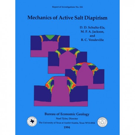
RI0224. Mechanics of Active Salt Diapirism, by D. D. Schultz-Ela, M. P. A. Jackson, and B. C. Vendeville. 56 p., 40 figs., 1994. Print.
To purchase this publication as a downloadable PDF, please order RI0224D.
ABSTRACT
An active diapir forcefully intrudes its overburden, driven by diapir pressure that overcomes the resistance of the overburden strength. Possible causes of the driving pressure are differential loading of the source layer and a density contrast with the overburden. Resisting forces derive from the mass of the roof block and resistance to the faulting and folding that accommodate the intrusion. This report describes the evolution of active diapirs and development of structures in their rock on the basis of analytical, physical, and numerical modeling.
For a typical density contrast between salt and a sedimentary overburden, a simple force balance demonstrates that the diapir height must be more than two-thirds to three-quarters the thickness of the surrounding overburden to initiate substantial active diapirism. Diapirs with widths less than the regional overburden thickness must be even taller to initiate active diapirism. Physical and numerical models show that typical structures of active diapirism are a central crestal graben flanked by relatively unstrained flaps that rotate upward and outward. Curved reverse faults can separate the flaps from the regional overburden. Normal faults in the crestal graben propagate downward, new faults being created farther outward as the roof arches over the rising diapir. Thin, wide roofs develop multiple grabens separating a relatively flat roof from the rotating flaps. In models leading to emergence, the piercing diapir evolves from a pointed crest to a progressively rounding and widening crest as the flaps rotate outward. Our numerical models show that overburden flexure contributes to early formation of active diapir structures, but piercement does not continue to emergence unless the diapir is very wide or tall relative to the overburden thickness. Active diapirism becomes progressively more difficult for diapir crests having the following shapes: rectangle (least difficult), round-cornered rectangle, semicircle, and triangle with a pointed crest (most difficult).
Keywords: active piercement, diapirism, finite-element models, forceful intrusion, halokinesis, physical models, salt domes, salt tectonics
CONTENTS
Abstract
Introduction
Geology of Active Diapirism
Structural Geometry
Evolutionary Paths to Active Diapirism
Evolutionary Paths from Active Diapirism
Conditions for Initiation of Active Diapirism
Previous Physical Modeling of Active Piercement
Physical Modeling of Conditions for Initiation of Active Diapirism
Analytical Model of Conditions for Initiation of Active Diapirism
Structural Evolution of Active Diapirism
Physical Modeling of Structural Evolution
Finite-Element Modeling of Structural Evolution
Model Parameters
Scaling to Nature
Initial Phase of Active Diapirism
Evolution of a Piercing Diapir
Transition to Emergence
Axisymmetric Model
Variations in Diapir Geometry
Asymmetric Models
Models Simulating Rock Properties
Effects of Constant-Stress Boundary Condition
Interlayer Slip in Roof
Comparison of Model Results
Conclusions
Acknowledgments
References
Figures
1. Interpreted seismic section of a salt diapir from Angola showing characteristics of active piercement
2. Schematic cross section showing the anatomy of an active diapir and nomenclature of faults associated with domes
3. Main structural styles associated with natural active diapirs
4. Interpreted seismic profile through the salt stock of Niendorf II, northern Germany
5. Cross section showing the Napoleonville salt dome, southern Louisiana
6. Cross section through the White Castle salt dome, southern Louisiana
7. Cross section through the Heide salt diapir, northern Germany
8. Cross section through the Sottorf and Meckelfeld salt diapirs, northern Germany
9. Meter-scale active diapirs of Neogene marls with gypsum cores piercing weak Quaternary gravels, Ebro Basin, Spain
10. Cross section through Bayou Blue field, southern Louisiana
11. Cross section through the Wathlingen-Hänigsen salt dome, northern Germany
12. Initial geometry of a typical physical model
13. Ridge B of figure 12 after 16 h of active piercement
14. Plot of physical model geometries on axes of diapir height and width
15. Configuration and variables for force-balance analysis
16. Plot of equations 7 and 14 showing conditions for which the major forces driving active diapirism equal those resisting it
17. Plots of conditions for initiation of active diapirism for different values of friction coefficient and density contrast
18. Cross sections in model of forced diapiric piercement showing progressive structural maturity
19. Apparatus for experiments in which the viscous material was forcefully injected up the diapir conduit
20. Evolution of cohesion and friction angle with equivalent plastic strain in finite-element models to simulate strain weakening
21. Basic finite-element mesh used for active diapir simulations and magnified view of top-left corner of the mesh, where all localized deformation occurs
22. Results from a finite-element model with diapir dimensions of hd*= 0.5625 and w* = 1.125
23. Model of figure 22 at a later stage after 136 s
24. Deformation in overburden above the diapir of figure 22 after 7.3 min
25. Contours of equivalent plastic strain in overburden above the diapir in figure 22 at 40 min
26. Outlines of model in diapir area at progressively longer run times and contours of displacement magnitude
27. Further outlines of model in diapir area at progressively longer run times
28. Contours of equivalent plastic strain in overburden above the diapir in figure 22 after 14.3 h
29. Comparison of active diapirism of a plane-strain salt wall with an axisymmetric salt stock with the same material properties and cross-sectional dimensions
30. Round-corner diapir model
31. Round-top diapir model
32. Triangular diapir model
33. Finite-element mesh with 2,376 elements for modeling an asymmetric active diapir with a sloping top surface
34. Plastic strain contours in the overburden surrounding two diapirs with differing degrees of asymmetry
35. Results from the center of the asymmetric active diapir model in figures 33 and 34b
36. Results from model with thin roof and rock properties that included negligible tensional strength
37. Elevations through time of selected points on the overburden top surface of the asymmetric active diapir model shown in figure 35
38. Results from model with constant-stress boundary condition, 0.5-km-thick roof, and rock properties
39. Results from model with constant-stress boundary condition, relatively thick roof, and rock properties
40. Model simulating interlayer slip in the roof above an active diapir with natural rock properties
Citation
Schultz-Ela, D. D., Jackson, M. P. A., and Vendeville, B. C., 1994, Mechanics of Active Salt Diapirism: The University of Texas at Austin, Bureau of Economic Geology, Report of Investigations No. 224, 56 p.
