Geological Circulars
-
Books & Reports
- Reports of Investigations
- Guidebooks
- Udden Series
- Geological Circulars
- Down To Earth
- Atlases of Major Oil and Gas Reservoirs
- Texas Memorial Museum Publications
- Environmental Geologic Atlas of the Texas Coastal Zone
- Mineral Resource Circulars
- Other Reports
- Seminars and Workshops
- Handbooks
- Submerged Lands of Texas
- Symposia
- Annual Reports
- Open File Reports
-
Maps & Cross Sections
- Thematic Maps
- Miscellaneous Maps, Charts & Sections
- Geologic Atlas of Texas
- STATEMAP Project Maps
- Geologic Quadrangle Maps
- Cross Sections
- Highway Geology Map
- Energy and Mineral Resource Maps
- Shoreline Change and Other Posters
- Wilcox Group, East Texas, Geological / Hydrological Folios
- Bouguer Gravity Atlas of Texas
- River Basin Regional Studies
- Featured Maps
- Posters
- Teachers & the Public
-
Geological Society Publications
- Gulf Coast Association of Geological Societies
- Alabama Geological Society
- Austin Geological Society
- Corpus Christi Geological Society
- Houston Geological Society
- Lafayette Geological Society
- Mississippi Geological Society
- New Orleans Geological Society
- South Texas Geological Society
- GCS SEPM Publications
- Historic BEG & UT Series

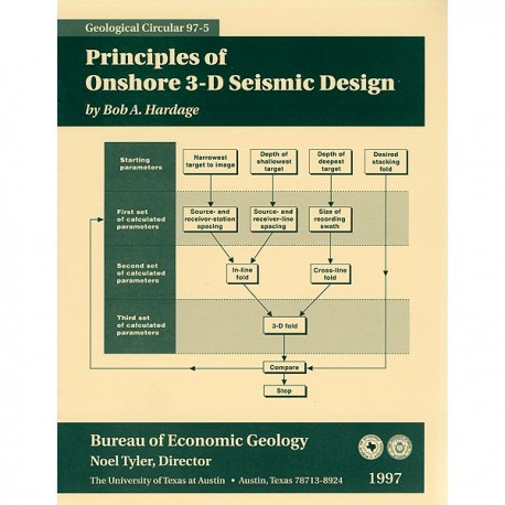
GC9705. Principles of Onshore 3-D Seismic Design, by B. A. Hardage. 23 p., 13 figs., 1997. ISSN: 0082-3309. Print.
To order this publication as a downloadable PDF, please order GC9705D.
ABSTRACT
The basic geometry of an onshore three-dimensional (3-D) seismic recording grid is based on five parameters: source-station spacing, receiver-station spacing, source-line spacing. receiver-line spacing, and recording swath size. At each onshore prospect considered for 3-D seismic imaging, these key design parameters can be specified by answering four simple questions: 1. What is the narrowest lateral dimension of the geologic targets that are to be imaged? 2. What is the depth of the shallowest target that must be imaged? 3. What is the depth of the deepest target that must be imaged? 4. What stacking fold is required to create an acceptable image at the depth of the principal target? The first three questions can be answered once the geology of the prospect is reasonably well known. The fourth question can be answered by (1) examining two-dimensional (2-D) seismic profiles that traverse the prospect area to estimate reflection signal quality, (2) examining 3-D seismic data recorded near the prospect, or (3) making a best guess, which is a risky and less desirable approach. Once these four questions are answered, the methodology described herein allows many onshore 3-D seismic recording grids to be designed without having to use complex computations or commercial design software. Some of the more technical aspects of 3-D seismic design, such as ensuring that there is a proper azimuth distribution of source-receiver offsets or creating a continuous numerical range of source-receiver offsets across the entire acquisition grid, are not considered in this simple treatise on first principles. The intent is to provide a procedure that allows nongeophysicists to plan simple 3-D surveys and to recognize flaws in proposed 3-D programs. This design procedure should be helpful to people who wish to verify the imaging capabilities of a particular 3-D seismic design but who do not access to, or wish to use, extensive computational resources.
Keywords: recording swath, stacking bin, stacking fold, three-dimensional design, three-dimensional seismic
CONTENTS
Abstract
Introduction
Key Design Parameters
Cost Rule: Minimize the Number of Source Stations
Narrowest Target to Image and Stacking Bin Size
Source-Station and Receiver-Station Spacings Depth of Shallowest Target and Its Implications: Source-Line and Receiver-Line Spacings
Depth of Primary (or Deepest) Target and Its Implication: Size of the Recording Swath
Stacking Fold Variation with Depth
3-D Stacking Fold
In-line Stacking Fold
Cross-line Stacking Fold
Example Calculation of 3-D Stacking Fold
Final Design Step: Comparing the Design Fold and the Desired Fold
The Even-Integer Rule
Summary
Acknowledgments
References
Epilogue
Figures
1. Sequence of planning steps that mill be followed to create an onshore 3-D seismic acquisition geometry
2. Oblique view of a horizontal grid of 3-D stacking bins
3. Example of the narowest feature that needs to be seen in the 3-D image
4. Section view of the Earth layering that is to be imaged.
5. An example of so~irce/receiver-lines pacings designed to image a shallow target at a depth of ZI
6. Recording swath designed to image a deep target at a depth Z
7. Vertical variation in stacking fold
8. Effect of number of active receivers on in-line stacking fold
9. Effect of source-station spacing on in-line stacking fold
10. Concept of cross-line stacking fold
11. The even-integer rule for onshore 3-D seismic design
12. Comparison of two 3-D recording swaths
13. Comparison of softtifare-generated stacking folds created by swath
Citation
Hardage, B. A., 1997, Principles of Onshore 3-D Seismic Design: The University of Texas at Austin, Bureau of Economic Geology, Geological Circular 97-5, 23 p.


